 01
Turning & turn-mill
Explore turning, front- and back-side machining, or parts that also need milling operations.
- Part size, material and blank form
- Operations, workholding and transfer
- Required machine configuration

CNC turning, precision grinding and project-based automation. Bring your requirements into focus before choosing a configuration.
Bearing automation & tooling references ↓Choose the closest application. We will help clarify what must be evaluated next.
01Explore turning, front- and back-side machining, or parts that also need milling operations.
 02
Start with the surface, geometry and inspection requirement—not only the worktable size.
 03
Evaluate machine tending, part transfer and production-line scope around the actual process.
| Your production need | Start by evaluating | Information to bring |
|---|---|---|
| Front- and back-side turning | Twin-spindle configuration and part transfer | Drawing, gripping surfaces, blank form and operation sequence |
| Turning plus milling features | Turn-mill configuration and tooling access | Feature geometry, tool needs, orientation and tolerances |
| Ground surfaces or profiles | Grinding method, workholding and machine capacity | Material, grinding area, allowance, finish and inspection method |
| Repeated loading and transfer | Machine tending and line integration | Part range, target output, changeovers and available floor space |
A starting point for evaluation, not a model recommendation or a guarantee of cycle time, accuracy or output.
A second spindle and milling capability answer different questions. First define which surfaces and features must be machined, then evaluate workholding, transfer and tooling with the engineering team.
Read the distributor sales brief ↗Separate worktable dimensions, grinding range and axis travel. Confirm the full workpiece envelope, fixture, grinding allowance and inspection criteria before selecting from the available grinding families.
Prepare the grinding requirements ↗Bearing-ring machining, machine tending and part transfer are starting points for discussion. Each project needs its own scope and technical review.
Blank, machining sequence, gripping and inspection requirements.
Infeed, outfeed, transfer interfaces, floor space and utilities.
Machine supply, integration, acceptance criteria and service responsibilities.
Explore Chuanhe's existing technical references alongside the selection guide. Start with the part family, then review the handling and fixture approach.
Use the bearing type as the starting point; bring the ring drawing and operation requirements for engineering review.
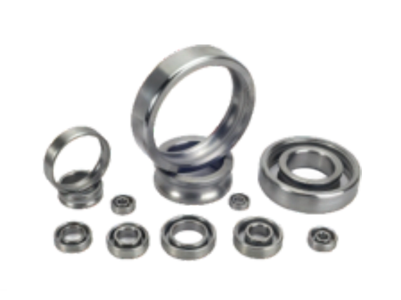
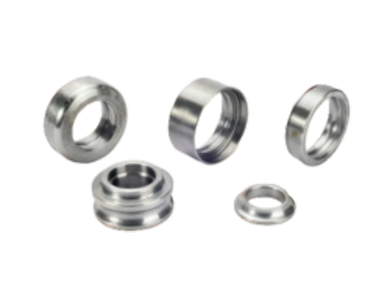
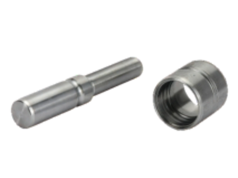
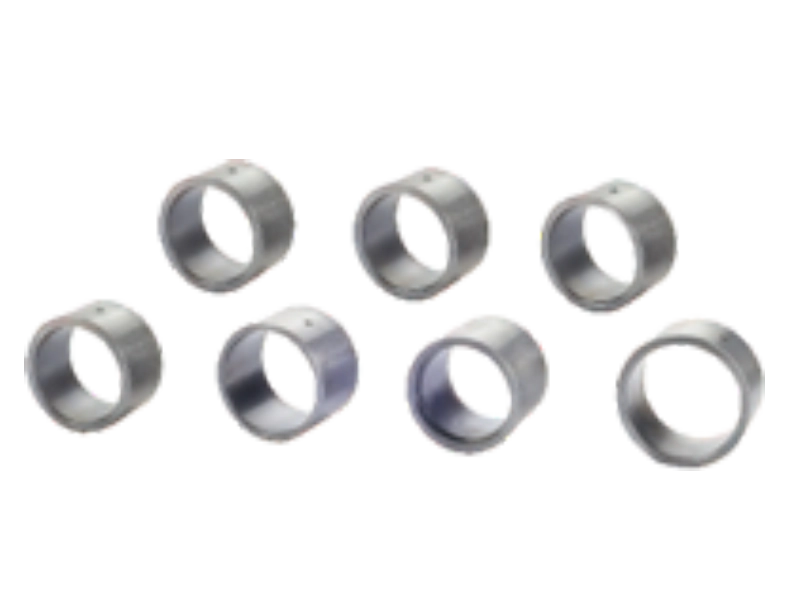
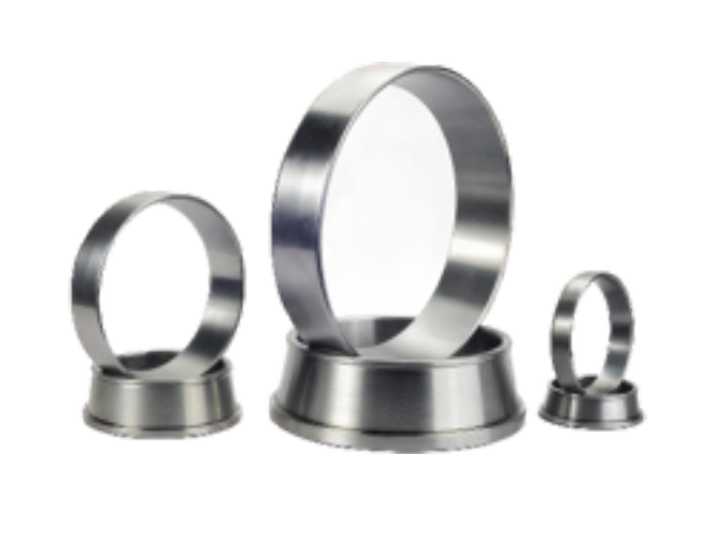
Application references, not a claim that every model covers every bearing family.
Explore P160 and P200 automation layout references. Review each layout against the actual part, process and changeover needs.
A material-channel arrangement shown in the existing technical library. Review part orientation, feeding, transfer and machining requirements together.
Prepare an automation project brief ↗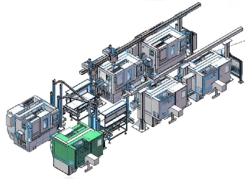
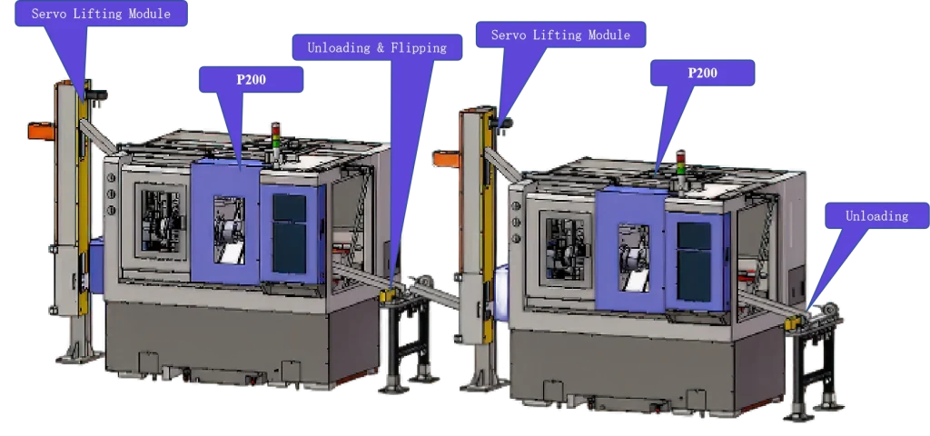
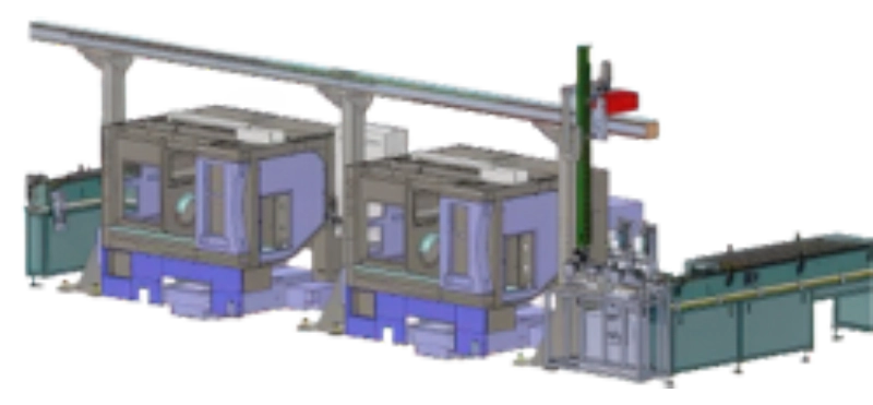
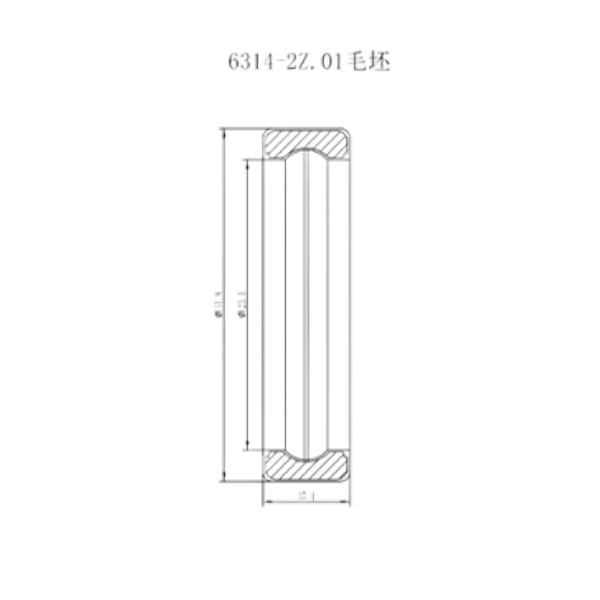
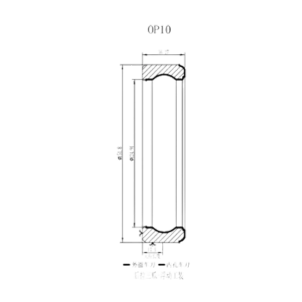
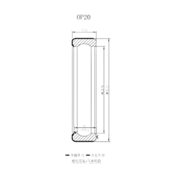
Machine specifications follow the P160 and P200 technical specifications for the FANUC system. Automation layouts and project-specific equipment must be assessed separately.
| Parameter | P160 | P200 |
|---|---|---|
| Max. turning diameter | Φ300 mm | Φ300 mm |
| Max. turning length | 320 mm | 305 mm |
| Chuck size | 6″ | 8″ |
| Spindle through-hole diameter | Φ56 mm | Φ66 mm |
| Bar capacity diameter | Φ42 mm | Φ52 mm |
| Max. spindle speed | 5000 rpm | 4500 rpm |
| Rated / Maximum Torque | 35/70 N·m | 99/180 N·m |
| X/Z guideway type | 35 mm linear guide | 35 mm linear guide |
| Overall Dimensions without Chip Conveyor (L × W × H) | 2200 × 1700 × 1700 mm | 2200 × 1700 × 1700 mm |
Spindle through-hole diameter and bar capacity are different specifications. Dimensions describe the machine, not a complete automated line. Final supply scope is subject to the agreed project specification.
Explore chuck and fixture examples. Review the gripping surfaces, part deformation, seating checks and coolant needs for each application.
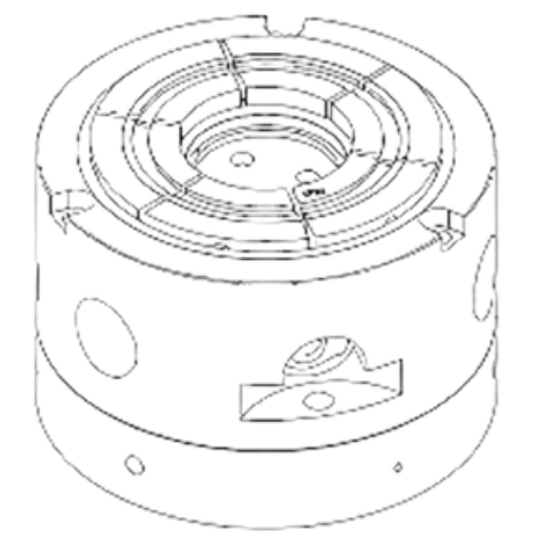
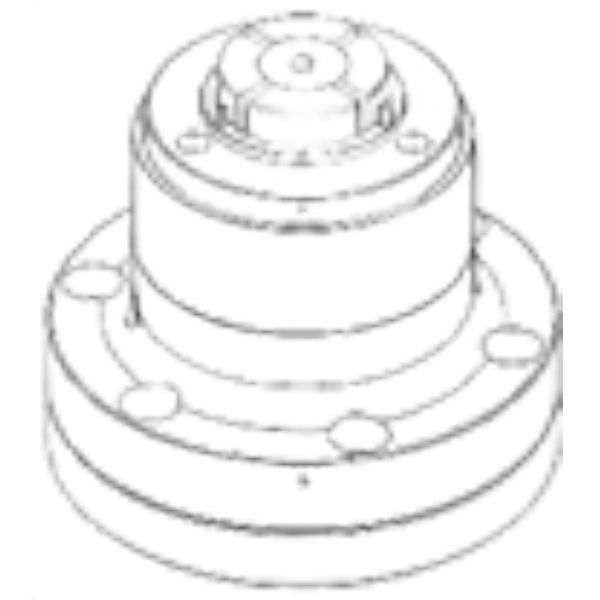
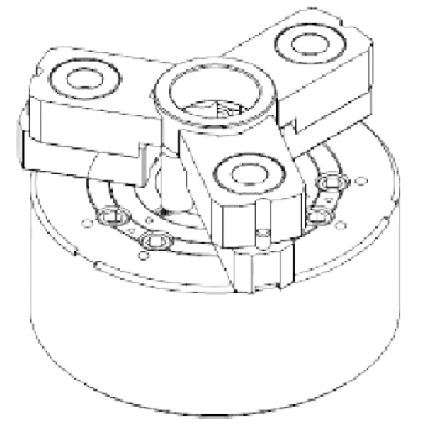
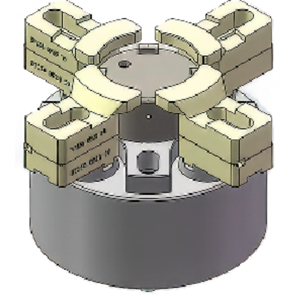
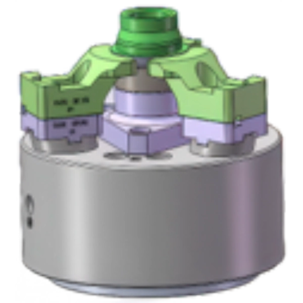
Fixture names and features follow the original library where consistent. They are examples for review, not the standard specification of every machine.
Selection prompts, customer-facing explanations and a project checklist—built around what the engineering team needs to know.
Two-page selection guide. Compare application needs and collect the right inputs.
Read guide ↗Download PDF · 2 pages · 114 KBRead the resources online or print the selected guide. No registration is required.
Drawing, material, operations and production targets.
Clarify suitability, configuration and missing information.
Review the proposed equipment and scope.
Agree commercial terms, acceptance and responsibilities.
Our application engineer will reply within 1 business day.
Initial reply only. Proposal timing depends on the project requirements.